Multibeam echosounder
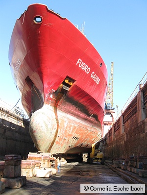
Survey vessels equipped with multi-sensor systems capture the topography of the seabed under the sealevel or the riverbed of inland waters. The three main components are the echosounder sensor for scanning the underwater suface, inclination sensors for deriving the pitsch and roll angles, and GNSS sensors for determining the yaw angle as well as the absolute ship position. All measurands of the individual systems are combined to georeferenced water depths which lead to seabed images for further analysis. However, an error-free combination of the measurement systems bases on geometrical relations of their reference frames, which are usually defined by markings on the sensor housing. The position and orientation of these reference frames are determined in a common local coordinate system during installation of the multibeam echosounder. The local reference frame is transferred to the ship-bound coordinate system in order to enable the operation of the echosounder later.
Tasks and challenges
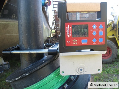
Depending on the system, the required accuracy of the orientation angles is up to 0.1°. The angles are derived from measured points or second-order surfaces (quadrics). Therefore, both the uncertainties of the point positions and the length of the base contribute to the accuracy of the derived angle. Due to the dimensions of the sensors, point position uncertainties of less than 0.1 mm are required.
In addition to the calibration, the mounting of the echosounder has to be monitored, too. The system consists of individual sensor plates of the transmitting and the receiving unit, which have to be mounted under the keel of the ship at specific bearing points. According to the manufacturer's specifications, the maximum deviation of a bearing point from the mean plane of all bearing points is 0.3 mm. For the metrological verification, a standard uncertainty of 0.1 mm in point position is derived perpendicular to the plane with an error probability of 0.1 %.
Measurement technology in use
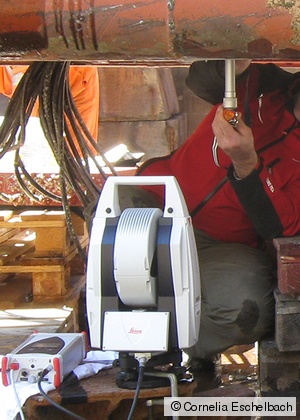
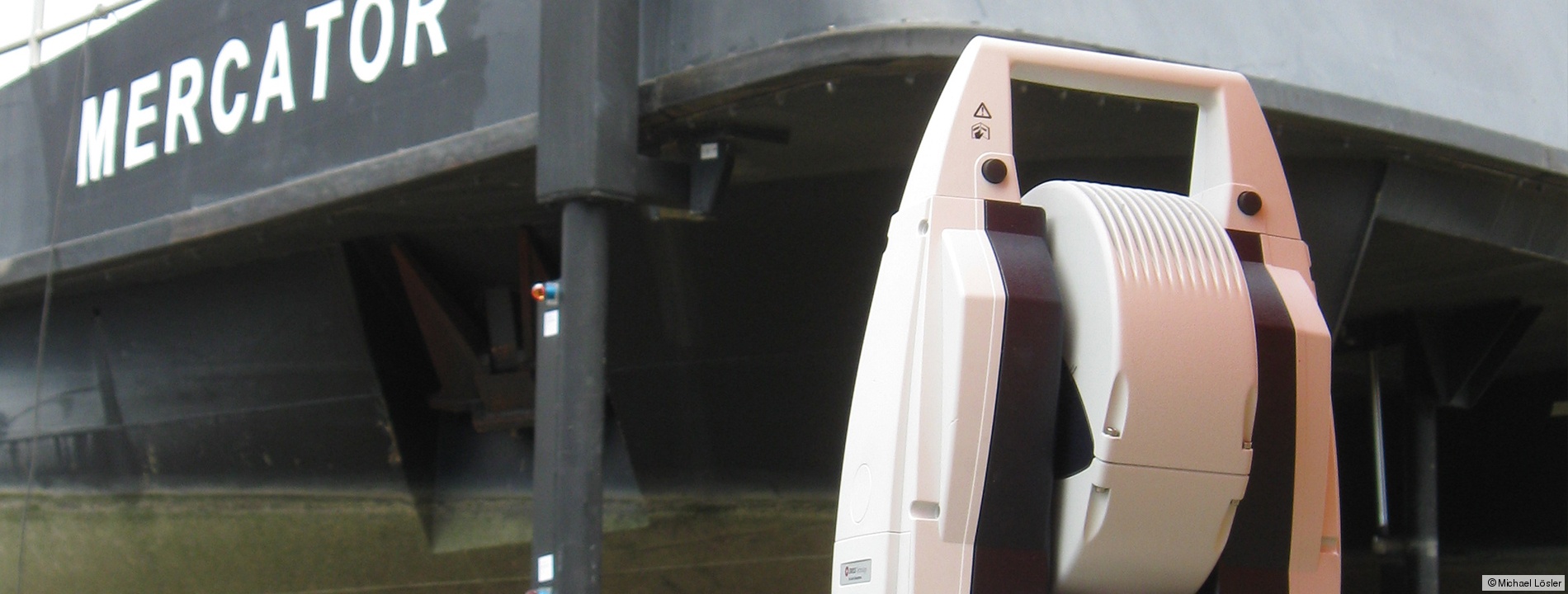
To meet these high accuracy requirements, the Leica AT401 mobile laser tracker is used. If the meteorological environmental parameters are taken into account and the transformation points for free stationing in the ship's coordinate system are chosen wisely, both the calibration and the adjustment of the echosounder can be carried out in a short time frame with very high accuracy.
During the adjustment process the adjustment parameters are displayed, and statistical methods are used to verify the final results. The determination of the installation orientations is performed in accordance with the requirements of the Federal Waterways and Shipping Agency.
Eschelbach, C. Overath, T.: Einsatz eines mobilen Lasertrackers zur hochpräzisen Justierung von Fächerlotsystemen bei Hochseevermessungsschiffen. In: Wieser, A. (eds): Ingenieurvermessung 14: Beiträge zum 17. Internationalen Ingenieurvermessungskurs, Zurich, 14-17 January 2014, Wichmann, pp. 347-360, 2014. ISBN: 978-3-87907-535-5
Prof. Dr.-Ing.
Cornelia Eschelbach
Phone: +49 (0) 69 1533-2356
cornelia.eschelbach(at)fb1.fra-uas.de
Dr.-Ing.
Michael Lösler
Phone: +49 (0) 69 1533-2784
michael.loesler(at)fb1.fra-uas.de
Address
Transfer centre
Steinbeis Transfer Centre Applied Geodesy
https://applied-geodesy.org
Member of SCGD
Member of the Society for Calibration of Geodetic Devices e.V. (SCGD)

